
1. Morton Effect in 23,000 HP Compressor Causing Vibration-Induced Shutdown
By Nelson L. Baxter, President of ABM Technical Services, CVA Cat IV, R.P.E.
Abstract: Large centrifugal compressors that are utilized in the process of producing compressed gases or liquid nitrogen, oxygen and argon are located all over the world. There are thousands of these large compressors in operation. These machines are unique in design and thus have some interesting problems. This paper presents a case history of a problem that occurs in this category of rotating equipment. This case illustrates how advanced analysis equipment can be utilized to capture amplitude and phase deviations, compressor surge and torsional responses from both start up transients and the torsional magnetic pole slip stimulus from synchronous motors.
Introduction: There are different centrifugal compressor designs. They are powered by either an induction motor or a large synchronous motor. The machine in this paper is of the basic arrangement described as follows. Synchronous motors are fairly common on the larger units because they can be used to control the power factor, thus reducing the cost of electricity. The motor drives a large bull gear at typically 1200 or 1800 RPM.
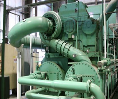
The bull gear drives the pinion shafts which have an impeller on either one or both ends. The diameter of the bull gear is several times that of the pinion shafts so the impeller speeds are several times the speed of the input shaft. The bearings are a tilt pad design. Aluminum labyrinth seals provide the shaft sealing. On the bigger compressors, the span between the motor and the bull gear will often be several feet in length. All of these design features play a key role in the vibration response of these compressors.

Bull gear driving small diameter pinion. This photograph is from a four-stage machine. Stages one and two are in the foreground with stages three and four in the background.
Morton Effect in 23,000 HP Compressor Causing Vibration-Induced Shutdown
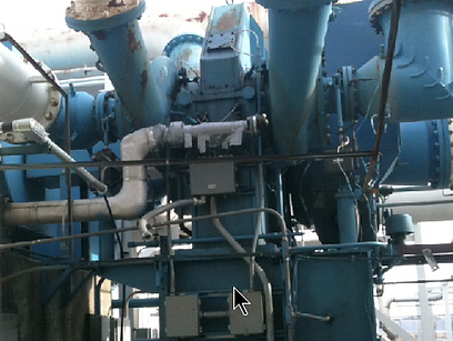
The vibration level on the Stage 3X, 3Y, 4X & 4Y probes of a large compressor, like the one seen here, would begin to oscillate. The time period of the oscillations varied from 6 to 7 minutes.
Oscillating Pattern Seen on Stage 3 and Stage 4 Proximity Probes
In some cases, the level would reach a peak, then after several cycles disappear. In other instances, the amplitude would continue to build until the unit shut down on a high-vibration trip.

A National Instruments 20-channel analyzer was connected to the Bently Nevada outputs on the entire machine. The compressor had fortunately been set up with X-Y probes on each of its eight stages. Each impeller also had a key phaser output, so it was possible to monitor the phase along with the amplitude when the transients occurred.
The pattern was very repeatable. As the vibration started to change, the phase also changed along with the amplitude. The pattern looked exactly like what occurs with a rub, but in this instance, the problem had been present for several months. The air seals were made of soft aluminum, so any rub that might have occurred would have quickly cleared rather than lasting for an extended period of time. The vibration when put into polar format appeared like that of a snail shell with the amplitude and phase slowly changing and the amplitude getting larger on each cycle (figure 3).
One Cycle of Morton Effect

Several 6- to 7-minute cycles show amplitude spiraling outward to a trip level.
figure 2
figure 1

This problem was determined to be the Morton effect. When this problem occurs, a complex series of events takes place. It starts with the residual unbalance causing a high spot on the shaft as it goes by the tilt pad bearing. The viscosity of the oil shearing causes a localized heating effect on the shaft at the high spot. This results in a small bow. Since these shafts operate above their first critical speed, the shaft throws out behind the resulting unbalance caused by the bow creating a new high spot and thus a new hot spot. This process continues, resulting in a slowly changing phase angle and an ever increasing amplitude.
As a temporary fix, a new shaft was installed with a lower level of unbalance to reduce the possibility of the process being triggered. The recommended long term solution was to design a new bearing to reduce the Morton effect. Increasing of the oil temperature to reduce the viscosity also had a positive effect.
figure 3
