
Understanding "Critical Speed"
- Apr 21, 2017
- 3 min read
I'm hoping to initiate a series of articles dealing with various topics in the Machine Condition Monitoring space. The intent is to keep most of these pretty short, and as entertaining as possible.
Anyone who has ever been unfortunate enough to be forced to sit through one of my presentations has been subjected to my "dummy’s" explanation of Critical Speed. I always pull out the tired example of driving your car when it has a badly unbalanced wheel… it shakes like mad at 50 or so, but if you push on through it and get up to 60 it runs pretty smoothly. This explanation of Critical Speed usually works in this setting, and I am rewarded to observe a whole room full of tiny little light bulbs flickering on over the heads of my attendees, who were previously nodding off to sleep.
But what the heck is really happening in your punished suspension? Why does the car act like that?
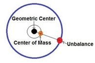
Inquiring minds are always looking for more information, and I am willing to provide as much as you can tolerate… so let’s take a look at a few concepts that you need to successful deal with Critical Speed. First, you need to understand what ‘imbalance’ is. In simplest terms, this is when the center of ROTATION and the center of MASS are not perfectly aligned on a rotating body.
The next basic to understand is that the unbalance FORCE will increase by the SQUARE of the speed of rotation. If you double the rotational speed, the FORCE increases by a factor of 4 times. The force vector is always aligned with the mass. Make sense so far? But what does the force generated actually do to the structure? In it's simplest form the force results in physical movement within the bearings or 'bending' deflection of the rotor, this movement is what we perceive as vibration. The amount of force generated does increase by the square of the rotational speed, but the actual deflection resulting, and the measurable vibration, is not directly linear and is affected by the mass, stiffness and structure of the rotating part.
OK, then there is this little problem called LAG, also known as PHASE. As the speed of rotation increases, the deflection generated does not stay perfectly aligned with the center of mass. The deflection vector is always falling farther and farther behind the mass center as speed increases.
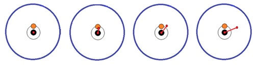
Rotation counter-clockwise – Lag trailing Mass Center as RPM & Generated Deflection Increasing
As with most of this stuff, this is not a linear sort of thing, and is affected by a host of physical factors, the mass of the rotating part, its composition and rigidity, the stiffness of the bearings etc. But the take away here is that while the force is going to double with speed, and the deflection (read vibration magnitude) vector is ALWAYS behind the center of mass.
‘First Critical’ is when the lag reaches 90 degrees! As speed increases above First Critical, the mass center becomes inverted, and the spin axis of the rotor is now opposite the deflection vector, essentially nulling the generated force. In a ‘perfect’ system, when the phase lag reached 180 degrees, the deflection vector, and the force vector would be completely cancel out resulting in zero vibration in the rotor!

Deflection Vector Increasing above 90 Degrees
In an idealized system, a plot of the Magnitude and Phase relationships looks like this:

For those paying attention this is a Bode plot (there will be a test later) Note that the phase changes gradually as the speed increase until it approaches the Critical Speed, in this plot that’s 6000 RPM. The phase lag begins to increase rapidly, transitioning through 90 degrees at the peak of the vibration magnitude. In a highly dampened system the phase change is much more gradual and the resultant forces generated at critical will be reduced.
The following illustrations provide a 3D look at the deflection of a simple rotor, the arched, red profile line illustrates the deflection of the rotor due to the unbalance force:
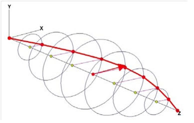
Below Critical
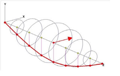
At Critical - 90 degrees Lag
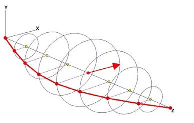
Above Critical – 180 degrees lag
[if !supportLineBreakNewLine]And, as you have probably guessed already since I have exceptionally intelligent readers, there is a SECOND Critical… and I’ll bet all of you can figure out when this occurs!

Now that this is all ‘perfectly ‘ clear, the next problem to recognize is that this ‘ideal’ rotor concept assumes that the rotor is in fact ‘rigid’, and we have only discussed the First BENDING MODE in our idealized machine! Most systems are more like a piece of half-cooked spaghetti, and are deflecting all over the map when you spin them up. A ‘flexible’ rotor can get really interesting. We’ll save Bending Modes for another post.
[endif]


Comments